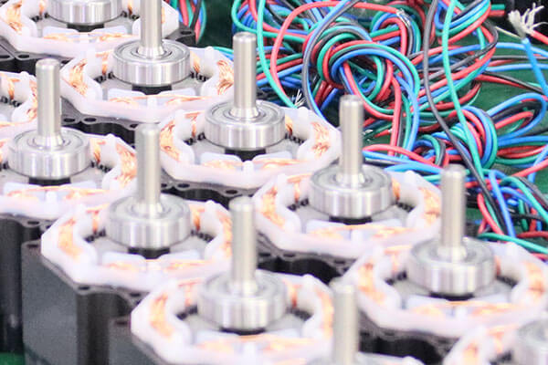
Introduction of Stepper Motor
What is a Stepper Motor?
A stepper motor is a type of electric motor that moves in precise, fixed steps rather than continuously rotating like a regular motor. It is commonly used in applications where precise position control is required, such as 3D printers, CNC machines, robotics, and camera platforms.
Stepper motors are a type of electric motor that convert electrical energy into rotational motion with remarkable precision. Unlike regular electric motors, which provide continuous rotation, stepper motors turn in discrete steps, making them ideal for applications requiring accurate positioning.
Every pulse of electricity sent to a stepper motor from its driver results in a precise movement—each pulse corresponds to a specific step. The speed at which the motor rotates directly correlates to the frequency of these pulses: the faster the pulses are sent, the quicker the rotation.
One of the key advantages of stepper motors is their easy control. Most drivers operate with 5-volt pulses, compatible with common integrated circuits. You can either design a circuit to generate these pulses or use a pulse generator from companies like BesFoc.
Despite their occasional inaccuracies—standard stepper motors have an accuracy of about ± 3 arc minutes (0.05°)—these errors do not accumulate with multiple steps. For instance, if a standard stepper motor makes one step, it will rotate 1.8° ± 0.05°. Even after a million steps, the total deviation is still just ± 0.05°, making them reliable for precise movements over long distances.
Additionally, stepper motors are known for their quick response and acceleration due to their low rotor inertia, allowing them to achieve high speeds quickly. This makes them particularly suited for applications that require short, rapid movements.
How Does a Stepper Motor Work?
A stepper motor works by dividing a full rotation into a number of equal steps. It uses electromagnets to create movement in small, controlled increments.
1. Inside the Stepper Motor
A stepper motor has two main parts:
Stator – the stationary part with coils (electromagnets).
Rotor – the rotating part, often a magnet or made of iron.
2. Movement by Magnetic Fields
When electric current flows through the stator coils, it creates magnetic fields.
These fields attract the rotor.
By turning the coils on and off in a specific sequence, the rotor is pulled step by step in a circular motion.
3. Step-by-Step Rotation
Each time a coil is energized, the rotor moves by a small angle (called a step).
For example, if a motor has 200 steps per revolution, each step moves the rotor 1.8°.
The motor can rotate forward or backward depending on the order of pulses sent to the coils.
4. Controlled by a Driver
A stepper motor driver sends electric pulses to the motor coils.
The more pulses, the more the motor turns.
Microcontrollers (like Arduino or Raspberry Pi) can control these drivers to move the motor precisely.
Stepper Motor System
The illustration below depicts a standard stepper motor system, which consists of several essential components that work together. The performance of each element influences the overall functionality of the system.
1. Computer or PLC:
At the heart of the system is the computer or programmable logic controller (PLC). This component acts as the brain, controlling not only the stepper motor but also the entire machine. It can perform various tasks, such as raising an elevator or moving a conveyor belt. Depending on the complexity needed, this controller can range from a sophisticated PC or PLC to a simple operator push button.
2. Indexer or PLC Card:
Next is the indexer or PLC card, which communicates specific instructions to the stepper motor. It generates the required number of pulses for movement and adjusts the pulse frequency to control acceleration, speed, and deceleration of the motor. The indexer can either be a standalone unit, like the BesFoc, or a pulse generator card that plugs into a PLC. Regardless of its form, this component is crucial for the motor’s operation.
3. Motor Driver:
The motor driver consists of four key parts:
Logic for Phase Control: This logic unit receives pulses from the indexer and determines which phase of the motor should be activated. Energizing the phases must follow a specific sequence to ensure proper motor operation.
Logic Power Supply: This is a low-voltage supply that powers the integrated circuits (ICs) within the driver, typically operating around 5 volts, based on the chip set or design.
Motor Power Supply: This supply provides the necessary voltage to power the motor, usually around 24 VDC, although it can be higher depending on the application.
Power Amplifier: This component consists of transistors that enable current to flow through the motor phases. These transistors are switched on and off in the correct sequence to facilitate the motor's movement.
4. Load:
Finally, all these components work together to move the load, which could be a lead screw, a disk, or a conveyor belt, depending on the specific application.
Types of Stepper Motors
There are three primary types of stepper motors:
Variable Reluctance (VR) Stepper Motors
These motors feature teeth on the rotor and stator but do not include a permanent magnet. As a result, they lack detent torque, meaning they do not hold their position when not energized.
Permanent Magnet (PM) Stepper Motors
PM stepper motors have a permanent magnet on the rotor but do not have teeth. While they typically exhibit less precision in step angles, they do provide detent torque, allowing them to maintain position when the power is turned off.
Hybrid Stepper Motors
BesFoc specializes exclusively in Hybrid stepper motors. These motors merge the magnetic properties of permanent magnets with the toothed design of variable reluctance motors. The rotor is axially magnetized, meaning that in a typical configuration, the top half is a north pole and the bottom half is a south pole.
The rotor consists of two toothed cups, each having 50 teeth. These cups are offset by 3.6°, allowing for precise positioning. When viewed from above, you can see that a tooth on the north pole cup aligns with a tooth on the south pole cup, creating an effective gearing system.
Hybrid stepper motors operate on a two-phase construction, with each phase containing four poles spaced 90° apart. Each pole in a phase is wound such that poles 180° apart have the same polarity, while polarities are opposite for those 90° apart. By reversing the current in any phase, the polarity of the corresponding stator pole can also be reversed, enabling the motor to convert any stator pole into a north or south pole.
The rotor of the stepper motor features 50 teeth, with a pitch of 7.2° between each tooth. As the motor operates, the alignment of the rotor teeth with the stator teeth can vary—specifically, it can be offset by three-quarter of a tooth pitch, half a tooth pitch, or a quarter of a tooth pitch. When the motor steps, it naturally takes the shortest path to realign itself, which translates to a movement of 1.8° per step (since 1/4 of 7.2° equals 1.8°).
Torque and accuracy in stepper motors are influenced by the number of poles (teeth). Generally, a higher pole count leads to improved torque and accuracy. BesFoc offers "High Resolution" stepper motors, which have half the tooth pitch of their standard models. These high-resolution rotors have 100 teeth, resulting in an angle of 3.6° between each tooth. With this setup, a movement of 1/4 of a tooth pitch corresponds to a smaller step of 0.9°.
As a result, the "High Resolution" models provide double the resolution of standard motors, achieving 400 steps per revolution compared to 200 steps per revolution in the standard models. Smaller step angles also lead to lower vibrations, since each step is less pronounced and more gradual.
Structure
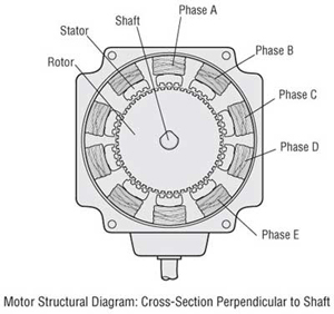
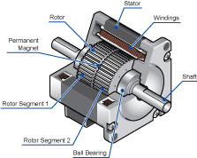
The diagram below illustrates a cross-section of a 5-phase stepper motor. This motor primarily consists of two main parts: the stator and the rotor. The rotor itself is made up of three components: rotor cup 1, rotor cup 2, and a permanent magnet. The rotor is magnetized in the axial direction; for instance, if rotor cup 1 is designated as the north pole, rotor cup 2 will be the south pole.
The stator features 10 magnetic poles, each equipped with small teeth and corresponding windings. These windings are designed so that each is connected to the winding of its opposite pole. When current flows through a pair of windings, the poles they connect magnetize in the same direction—either north or south.
Each opposing pair of poles forms one phase of the motor. Given that there are 10 magnetic poles in total, this results in five distinct phases within this 5-phase stepper motor.
Importantly, each rotor cup has 50 teeth along their outer perimeter. The teeth on rotor cup 1 and rotor cup 2 are mechanically offset from one another by half a tooth pitch, allowing for precise alignment and movement during operation.
Speed-Torque
Understanding how to read a speed-torque curve is crucial, as it provides insights into what a motor is capable of achieving. These curves represent the performance characteristics of a specific motor when paired with a particular driver. Once the motor is operational, its torque output is influenced by the type of drive and the applied voltage. As a result, the same motor can exhibit significantly different speed-torque curves depending on the driver used.
BesFoc provides these speed-torque curves as a reference. If you utilize a motor with a driver that has similar voltage and current ratings, you can expect comparable performance. For an interactive experience, please refer to the speed-torque curve provided below:
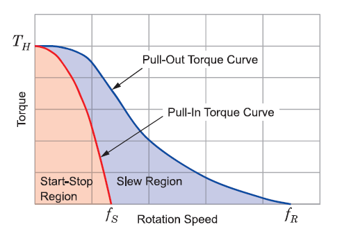
Reading a Speed-Torque Curve
Holding Torque
This is the amount of torque produced by the motor when it is at rest, with the rated current flowing through its windings.
Start/Stop Region
This section indicates the torque and speed values at which the motor can start, stop, or reverse instantaneously.
Pull-In Torque
These are the torque and speed values that allow the motor to start, stop, or reverse while remaining in synchronism with the input pulses.
Pullout Torque
This refers to the torque and speed values at which the motor can operate without stalling, maintaining synchronization with the input phases. It represents the maximum torque the motor can deliver during operation.
Maximum Starting Speed
This is the highest speed at which the motor can start running when there is no load applied.
Maximum Running Speed
This indicates the fastest speed the motor can achieve while running with no load.
To operate within the region between pull-in and pullout torque, the motor must initially start in the start/stop region. As the motor begins to run, the pulse rate is gradually increased until the desired speed is achieved. To stop the motor, the speed is then decreased until it falls below the pull-in torque curve.
Torque is directly proportional to the current and the number of wire turns in the motor. To increase torque by 20%, the current should also be increased by approximately 20%. Conversely, to decrease torque by 50%, the current should be reduced by 50%.
However, due to magnetic saturation, there’s no benefit in increasing the current beyond twice the rated current, as beyond this point, further increases won’t enhance torque. Operating at around ten times the rated current poses the risk of demagnetizing the rotor.
All of our motors are equipped with Class B insulation, which can withstand temperatures up to 130°C before the insulation starts to degrade. To ensure longevity, we recommend maintaining a temperature differential of 30°C from the inside to the outside, meaning the exterior case temperature should not exceed 100°C.
Inductance plays a significant role in high-speed torque performance. It explains why motors do not exhibit endlessly high levels of torque. Each winding of the motor has distinct values of inductance and resistance. The inductance measured in henrys, divided by the resistance in ohms, results in a time constant (in seconds). This time constant indicates how long it takes for the coil to reach 63% of its rated current. For instance, if the motor is rated for 1 amp, after one time constant, the coil will reach approximately 0.63 amps. It typically takes about four to five time constants for the coil to reach full current (1 amp). Since torque is proportional to current, if the current only reaches 63%, the motor will produce about 63% of its maximum torque after one time constant.
At low speeds, this delay in current buildup is not an issue since the current can effectively enter and exit the coils quickly, allowing the motor to deliver its rated torque. However, at high speeds, the current cannot increase quickly enough before the next phase switches, resulting in reduced torque.
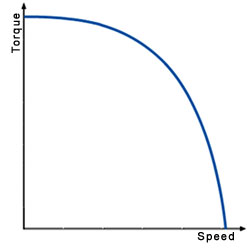
Driver Voltage Impact
Driver voltage significantly affects the high-speed performance of a stepper motor. A higher ratio of drive voltage to motor voltage leads to improved high-speed capabilities. This is because elevated voltages allow current to flow into the windings more rapidly than the 63% threshold previously discussed.
Vibration
When a stepper motor transitions from one step to the next, the rotor does not stop instantly at the target position. Instead, it moves past the final position, then is drawn back, overshooting in the opposite direction, and continues to oscillate back and forth until it eventually comes to a stop. This phenomenon, referred to as "ringing," occurs with each step the motor takes (see the interactive diagram below). Much like a bungee cord, the rotor’s momentum carries it beyond its stopping point, causing it to "bounce" before settling at rest. In many cases, however, the motor is instructed to move to the next step before it has fully stopped.
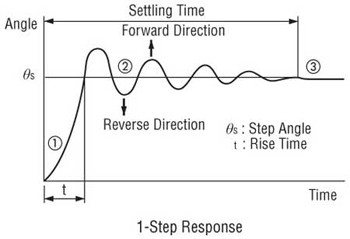
The graphs below illustrate the ringing behavior of a stepper motor under various loading conditions. When the motor is unloaded, it exhibits significant ringing, which translates to increased vibration. This excessive vibration can lead to the motor stalling when it is either unloaded or lightly loaded, as it may lose synchronization. Therefore, it is essential to always test a stepper motor with an appropriate load.
The other two graphs depict the motor's performance when loaded. Properly loading the motor helps to stabilize its operation and reduce vibration. Ideally, the load should require between 30% to 70% of the motor's maximum torque output. Additionally, the inertia ratio of the load to the rotor should fall between 1:1 and 10:1. For shorter and quicker movements, it is preferable for this ratio to be closer to 1:1 to 3:1.

Assistance from BesFoc
BesFoc's application specialists and engineers are available to help with proper motor sizing.
Resonance and Vibration
A stepper motor will experience significantly increased vibrations when the input pulse frequency coincides with its natural frequency, a phenomenon known as resonance. This often occurs around 200 Hz. At resonance, the overshooting and undershooting of the rotor are greatly amplified, increasing the likelihood of missing steps. While the specific resonant frequency can vary with load inertia, it typically hovers around 200 Hz.
Step Loss in 2-Phase Motors
2-phase stepper motors can only miss steps in groups of four. If you notice step loss occurring in multiples of four, it indicates that vibrations are causing the motor to lose synchronization or that the load may be excessive. Conversely, if missed steps are not in multiples of four, there is a strong indication that either the pulse count is incorrect or electrical noise is influencing performance.
Mitigating Resonance
Several strategies can help mitigate resonance effects. The simplest approach is to avoid operating at the resonant speed altogether. Since 200 Hz corresponds to approximately 60 RPM for a 2-phase motor, it is not an extremely high speed. Most stepper motors have a maximum starting speed of around 1000 pulses per second (pps). Therefore, in many cases, you can initiate the motor operation at a speed higher than the resonant frequency.
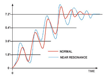
If you need to start the motor at a speed that is below the resonant frequency, it’s important to accelerate quickly through the resonant range to minimize the effects of vibration.
Reducing Step Angle
Another effective solution is to use a smaller step angle. Larger step angles tend to result in greater overshooting and undershooting. If the motor has a short distance to travel, it won't generate enough force (torque) to overshoot significantly. By reducing the step angle, the motor experiences less vibration. This is one reason why half-stepping and microstepping techniques are so effective in reducing vibrations.
Be sure to select the motor based on the load requirements. Proper motor sizing can lead to better overall performance.
Using Dampers
Dampers are another option to consider. These devices can be fitted onto the back shaft of the motor to absorb some of the vibrational energy, helping to smooth out the operation of a vibrating motor in a cost-effective manner.
5-Phase Stepper Motors
A relatively new advancement in stepper motor technology is the 5-phase stepper motor. The most noticeable difference between 2-phase and 5-phase motors (see the interactive diagram below) is the number of stator poles: 2-phase motors have 8 poles (4 per phase), while 5-phase motors feature 10 poles (2 per phase). The rotor design is similar to that of a 2-phase motor.
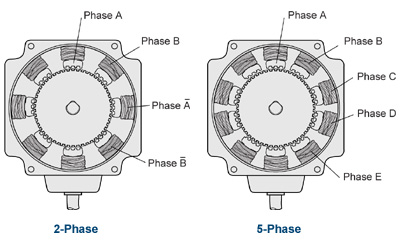
In a 2-phase motor, each phase moves the rotor by 1/4 tooth pitch, while in a 5-phase motor, the rotor moves 1/10 of a tooth pitch due to its design. With a tooth pitch of 7.2°, the step angle for the 5-phase motor becomes 0.72°. This construction allows the 5-phase motor to achieve 500 steps per revolution, compared to the 2-phase motor's 200 steps per revolution, providing a resolution that is 2.5 times greater than that of the 2-phase motor.
A higher resolution leads to a smaller step angle, which significantly reduces vibration. Since the step angle of the 5-phase motor is 2.5 times smaller than that of the 2-phase motor, it experiences much lower ringing and vibrations. In both motor types, the rotor must overshoot or undershoot by more than 3.6° to miss steps. With the 5-phase motor’s step angle of only 0.72°, it becomes nearly impossible for the motor to overshoot or undershoot by such a margin, resulting in a very low likelihood of losing synchronization.
Drive Methods
There are four primary drive methods for stepper motors:
Wave Drive (Full Step)
2 Phases On (Full Step)
1-2 Phases On (Half Step)
Microstep
Wave Drive
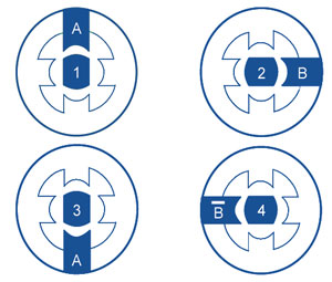
In the diagram below, the wave drive method is simplified to illustrate its principles. Each 90° turn depicted in the illustration represents 1.8° of rotor rotation in a real motor.
In the wave drive method, also known as the 1-phase ON method, only one phase is energized at a time. When the A phase is activated, it creates a south pole that attracts the north pole of the rotor. Then, the A phase is turned off and the B phase is turned on, causing the rotor to rotate 90° (1.8°), and this process continues with each phase being energized individually.
The wave drive operates with a four-step electrical sequence to rotate the motor.
2 Phases On
In the "2 Phases On" drive method, both phases of the motor are continuously energized.
As illustrated below, each 90° turn corresponds to a 1.8° rotor rotation. When both A and B phases are energized as south poles, the north pole of the rotor is attracted equally to both poles, causing it to align directly in the middle. As the sequence progresses and the phases are activated, the rotor will rotate to maintain alignment between the two energized poles.
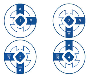
The "2 Phases On" method operates using a four-step electrical sequence to rotate the motor.
BesFoc's standard 2-phase and 2-phase M type motors utilize this "2 Phases On" drive method.
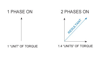
The main advantage of the "2 Phases On" method over the "1 Phase On" method is torque. In the "1 Phase On" method, only one phase is activated at a time, resulting in a single unit of torque acting on the rotor. In contrast, the "2 Phases On" method energizes both phases simultaneously, producing two units of torque. One torque vector acts at the 12 o’clock position and the other at the 3 o’clock position. When these two torque vectors are combined, they create a resultant vector at a 45° angle with a magnitude that is 41.4% greater than that of a single vector. This means that using the "2 Phases On" method allows us to achieve the same step angle as the "1 Phase On" method while delivering 41% more torque.
Five-phase motors, however, operate somewhat differently. Instead of employing the "2 Phases On" method, they utilize the "4 Phases On" method. In this approach, four of the phases are activated simultaneously each time the motor takes a step.
As a result, the five-phase motor follows a 10-step electrical sequence during operation.
1-2 Phases On (Half Step)
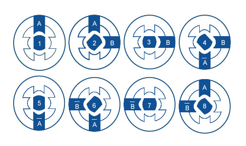
The "1-2 Phases On" method, also known as half stepping, combines the principles of the previous two methods. In this approach, we first energize the A phase, causing the rotor to align. While keeping the A phase energized, we then activate the B phase. At this point, the rotor is equally attracted to both poles and aligns in the middle, resulting in a rotation of 45° (or 0.9°). Next, we turn off the A phase while continuing to energize the B phase, allowing the motor to take another step. This process continues, alternating between energizing one phase and two phases. By doing so, we effectively cut the step angle in half, which helps reduce vibrations.
For a 5-phase motor, we employ a similar strategy by alternating between 4 phases on and 5 phases on.
The half-step mode consists of an eight-step electrical sequence. In the case of a five-phase motor using the "4-5 Phases On" method, the motor goes through a 20-step electrical sequence.
Microstep
(More information can be added about microstepping if needed.)
Microstepping
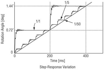
Microstepping is a technique used to make smaller steps even finer. The smaller the steps, the higher the resolution and the better the motor's vibration characteristics. In microstepping, a phase is neither fully on nor fully off; instead, it is partially energized. Sine waves are applied to both Phase A and Phase B, with a phase difference of 90° (or 0.9° in a five-phase stepper motor).
When the maximum power is applied to Phase A, Phase B is at zero, causing the rotor to align with Phase A. As the current to Phase A decreases, the current to Phase B increases, allowing the rotor to take tiny steps toward Phase B. This process continues as the current cycles between the two phases, resulting in smooth microstepping motion.
However, microstepping does present some challenges, mainly regarding accuracy and torque. Since the phases are only partially energized, the motor typically experiences a torque reduction of about 30%. Additionally, because the torque differential between steps is minimal, the motor might struggle to overcome a load, which can result in situations where the motor is commanded to move several steps before it actually begins to move. In many cases, incorporating encoders is necessary to create a closed-loop system, though this adds to the overall cost.
Stepper Motor Systems
Open Loop Systems
Closed Loop Systems
Servo Systems
Open Loop
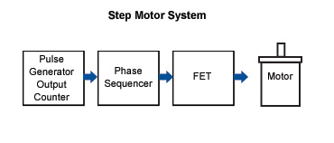
stepper motors are typically designed as open loop systems. In this configuration, a pulse generator sends pulses to the phase sequencing circuit. The phase sequencer determines which phases should be turned on or off, as previously described in the full step and half step methods. The sequencer controls the high-power FETs to activate the motor.
However, in an open loop system, there is no verification of position, meaning there’s no way to confirm whether the motor has executed the commanded movement.
Closed Loop
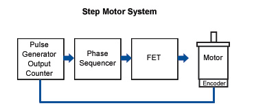
One of the most common methods for implementing a closed-loop system is by adding an encoder to the back shaft of a double-shafted motor. The encoder consists of a thin disc marked with lines that rotates between a transmitter and a receiver. Each time a line passes between these two components, it generates a pulse on the signal lines.
These output pulses are then fed back to the controller, which keeps a count of them. Typically, at the end of a movement, the controller compares the number of pulses it sent to the driver with the number of pulses received from the encoder. A specific routine is executed whereby, if the two counts differ, the system adjusts to correct the discrepancy. If the counts match, it indicates that no error has occurred, and motion can continue smoothly.
Drawbacks of Closed Loop Systems
The closed-loop system comes with two main drawbacks: cost (and complexity) and response time. The inclusion of an encoder adds to the overall expense of the system, along with the increased sophistication of the controller, which contributes to the total cost. Additionally, because corrections are made only at the end of a movement, this can introduce delays into the system, potentially slowing down response times.
Servo System
An alternative to closed-loop stepper systems is a servo system. Servo systems typically use motors with a low pole count, enabling high-speed performance but lacking inherent positioning capability. To convert a servo into a positional device, feedback mechanisms are needed, often using an encoder or resolver along with control loops.
In a servo system, the motor is activated and deactivated until the resolver indicates that a specified position has been reached. For instance, if the servo is instructed to move 100 revolutions, it begins with the resolver count at zero. The motor runs until the resolver count reaches 100 revolutions, at which point it turns off. If there’s any positional shift, the motor is reactivated to correct the position.
The response of the servo to positional errors is influenced by a gain setting. A high gain setting allows the motor to react quickly to changes in error, while a low gain setting results in a slower response. However, adjusting gain settings can introduce time delays into the motion control system, affecting overall performance.
AlphaStep Closed Loop Stepper Motor Systems
AlphaStep is BesFoc's innovative stepper motor solution, featuring an integrated resolver that offers real-time position feedback. This design ensures that the exact position of the rotor is known at all times, enhancing the precision and reliability of the system.
AlphaStep Closed Loop Stepper Motor Systems
The AlphaStep driver features an input counter that tracks all pulses sent to the drive. Simultaneously, feedback from the resolver is directed to a rotor position counter, allowing for continuous monitoring of the rotor's position. Any discrepancies are recorded in a deviation counter.
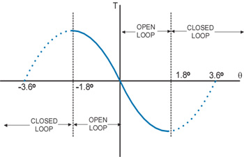
Typically, the motor operates in open loop mode, generating torque vectors for the motor to follow. However, if the deviation counter indicates a discrepancy greater than ±1.8°, the phase sequencer activates the torque vector at the upper section of the torque displacement curve. This generates maximum torque to realign the rotor and bring it back into synchronism. If the motor is off by several steps, the sequencer energizes multiple torque vectors at the high end of the torque displacement curve. The driver can handle overload conditions for up to 5 seconds; if it fails to restore synchronism within this timeframe, a fault is triggered, and an alarm is issued.
A remarkable feature of the AlphaStep system is its ability to make real-time corrections for any missed steps. Unlike traditional systems that wait until the end of a move to correct any errors, the AlphaStep driver takes corrective action as soon as the rotor falls outside the 1.8° range. Once the rotor is back within this limit, the driver reverts to open loop mode and resumes the appropriate phase energizations.
The accompanying graph illustrates the torque displacement curve, highlighting the operational modes of the system—open loop and closed loop. The torque displacement curve represents the torque generated by a single phase, achieving maximum torque when the rotor position deviates by 1.8°. A step can only be missed if the rotor overshoots by more than 3.6°. Because the driver takes control of the torque vector whenever the deviation exceeds 1.8°, the motor is unlikely to miss steps unless it experiences an overload lasting more than 5 seconds.
Step Accuracy of AlphaStep
Many people mistakenly believe that the step accuracy of the AlphaStep motor is ±1.8°. In reality, the AlphaStep has a step accuracy of 5 arc minutes (0.083°). The driver manages the torque vectors when the rotor is outside the 1.8° range. Once the rotor falls within this range, the rotor teeth align precisely with the torque vector being generated. The AlphaStep ensures that the correct tooth aligns with the active torque vector.
The AlphaStep series comes in various versions. BesFoc offers both round shaft and geared models with multiple gear ratios to either enhance resolution and torque or to minimize reflected inertia. Most versions can be equipped with a fail-safe magnetic brake. Additionally, BesFoc provides a 24 VDC version called the ASC series.
Conclusion
In conclusion, stepper motors are highly suitable for positioning applications. They allow for precise control of both distance and speed simply by varying the pulse count and frequency. Their high pole count enables accuracy, even when operating in open loop mode. When properly sized for a specific application, a stepper motor will not miss steps. Moreover, because they don’t require positional feedback, stepper motors are a cost-effective solution.
English
العربية
Français
Русский
Español
Português
Deutsch
italiano
日本語
한국어
Nederlands
Tiếng Việt
ไทย
Polski
Türkçe
ພາສາລາວ
ភាសាខ្មែរ
Bahasa Melayu
ဗမာစာ
Filipino
Bahasa Indonesia
magyar
Română
Čeština
Монгол
қазақ
Српски
हिन्दी
فارسی
Slovenčina
Slovenščina
Norsk
Svenska
українська
Ελληνικά
Suomi
Հայերեն
עברית
Latine
Dansk
Shqip
বাংলা
Hrvatski
Afrikaans
Gaeilge
Eesti keel
Oʻzbekcha
latviešu
Azərbaycan dili
Български
Català


